How To Effectively Inspect Friction Stir Welds in Manufactured Components for the Aerospace Industry
Ask an expertFriction stir welding is a solid-state joining process frequently used in the aerospace industry. Depending on manufacturing parameters such as rotation and translation speed, the friction stir welding process sometimes creates discontinuities within the weld; therefore, a non-destructive testing method must be applied to ascertain weld integrity. High productivity, efficiency, and accuracy are at the core of these mandatory assessments during the quality assurance stage of newly manufactured aircraft.
The Challenge
Reduce time spent to inspect areas of interest during ultrasonic examination of friction stir welds found in aerospace components.
Friction stir welding has been known to pose certain inspection challenges when it comes to quality assurance checks. Conventional non-destructive testing techniques tend to be time consuming, unreliable, require setup and calibration of multiple probes, and often do not provide adequate coverage.
Select advanced phased array ultrasonic testing techniques have previously been considered for replacing conventional ultrasonic testing and radiographic testing of friction stir welds in newly manufactured aerospace components. However, the most common inspection method, based on phased array ultrasonic testing, has several limitations in terms of industrialization as well as performance and reliability. The frequently used inspection technique typically requires three different beam angles to detect flaws parallel to the weld center line. The standard inspection offering uses multiple probes and requires each probe be aligned and calibrated, making for a lengthy process. Reliability remains an issue as transverse or skewed flaw types are not reliably detected with a standard probe design. In addition, weld surface conditions and flashing can prevent adequate coverage of the weld area with contact solution. Therefore, industry seeks a more productive solution with trusted inspection results.
The Solution
A dedicated probe design implements multiple simultaneous inspection configurations, minimizing the time required for setup.
The challenges of inspecting friction stir welds have been answered with Eddyfi Technologies’ optimized probes and high-end phased array ultrasonic testing instruments with dedicated onboard software.
To assess the inspection configuration and associated detection performance, a standard 10 MHz 64-element probe was used to scan a friction stir weld sample with artificial indications that simulate realistic friction stir weld discontinuities. This enables a performance baseline to demonstrate the benefits and improvements that the new optimized design offers compared to standard commercially available solutions.
Figure 1
Bottom view sample aluminum friction stir weld, t = 6.3 millimeters (0.24 inches), containing planar and volumetric artificial reflectors with various orientations, located at outer diameter (OD), inner diameter (ID), and mid-wall.
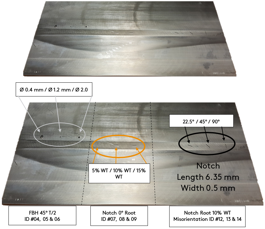
Figure 2
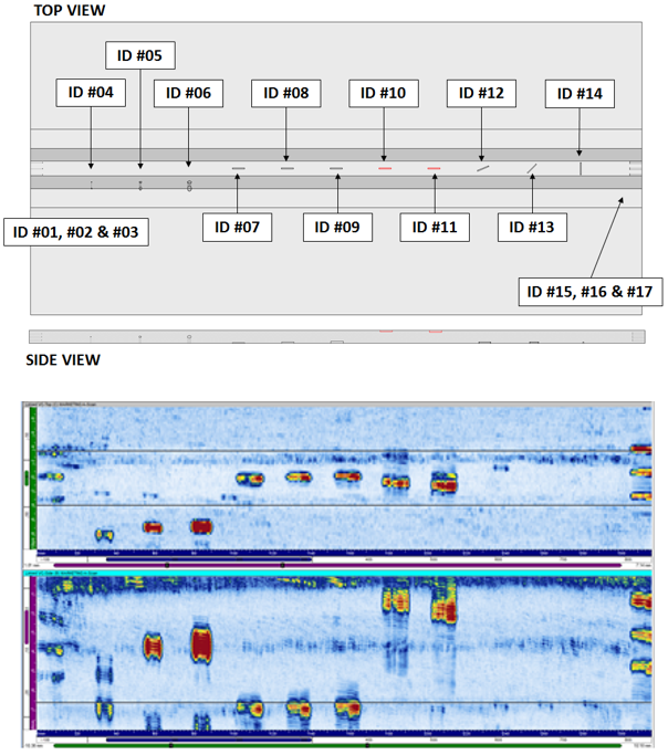
Friction stir weld plate indications map and scan results. 6.6 millimeters (0.25 inches) thick with three types of typical friction stir weld flaws, side-drilled holes (SDH), flat bottom holes (FBH), and notches, each at different depths or orientations.
The 1D linear array probe has an optimized 128-element design to meet the objectives of simplifying and optimizing the friction stir weld inspection process. The probe is capable of generating ±45-degree shear waves inside the material as well as 0-degree longitudinal waves with a single probe orientation, as displayed in Figure 3.
The probe parameters such as element size, pitch, and center frequency have been optimized to drastically enhance the steering capability when compared to the standard probe, while keeping an acceptable sensitivity. This modern design also has the direct advantage of providing a much finer resolution between focal laws which leads to better sizing capability.
Figure 3
Multiple beam configuration using a single probe position

Examination Techniques for Weld Center Line Flaws
To maximize efficiency and bypass geometrical constraints, testing is done in an immersion tank which allows for adequate coupling on “as welded” surface conditions. For both specimens, the optimized probe scans are performed in a similar manner. The inspections were realized using a single probe configuration, simultaneously generating -45-degree shear wave (SW), +45-degree SW and 0-degree longitudinal wave (LW). The probe is mounted on a guided probe head to ensure perfect orientation between the probe and the surface of the specimen as displayed in Figure 4.
Figure 4
Optimized probe inspection setup
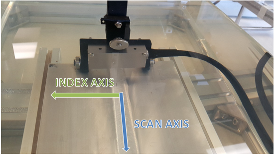
Figure 5 presents a side-by-side comparison of the scan results obtained by using the standard (left) and the optimized (right) probes.
Figure 5
Friction Stir Weld Plate-01 45SW Linear Scan

Figure 6
Friction Stir Weld Plate-01 0LW Linear Scan

Figure 7
Friction Stir Weld Plate-01 0LW Optimized Probe Backwall

Figure 8
Merged data group allows detection of all artificial reflectors with good SNR
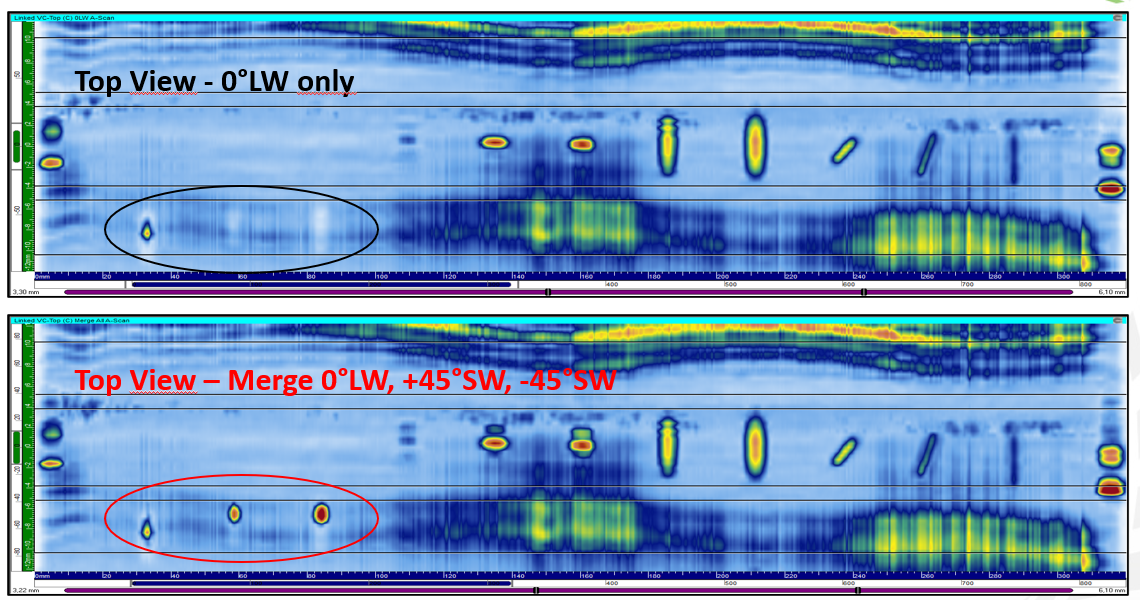
Figure 9
45° SW angle beam techniques generate tip diffraction signals, allowing for accurate through-wall sizing of planar flaws

ID Notch [h = 1.65 millimeters (0.06 inches)], Measured Height = 1.5 millimeters (0.05 inches) & ID Notch [h = 3.3 millimeters (0.12 inches)], Measured Height = 3.2 millimeters (0.12 inches)
Examination Techniques for Transverse Flaws
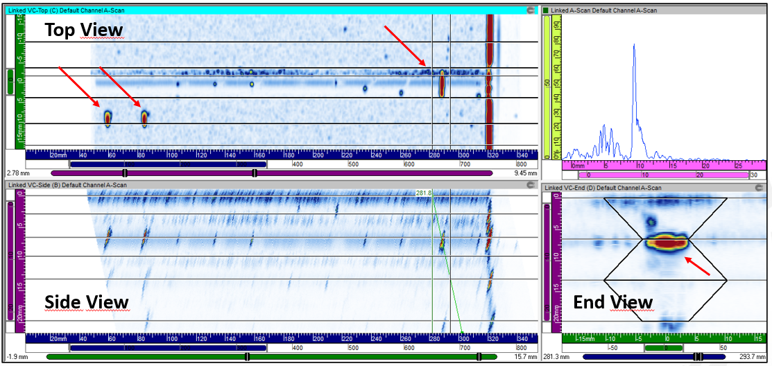
For the examination of transverse flaws, the linear electronic scanning is performed using two beam angles (+45° SW and -45° SW) and a probe inclination in secondary plane. Just as it is possible for typical flaw examination, the techniques are easily applicable in a single scanning sequence, and the volumetric merge is done to maximize the data analysis efficiency.
Figure 10
Dedicated inspection technique with inclined probe provides excellent detection capability on transverse flaws.
However, the probe is only part of the non-destructive testing solution. Two inspection instruments can be paired with the optimized phased array ultrasonic testing probe, the Cypher® and the Panther™ 2. High-performance, a portable rugged construction, combined with best-in-class embedded software, Cypher offers users fast data acquisition and probe support without the need for external software. Intuitive onboard recording is also embedded in the unit. For a desktop scalable system, Panther is the answer as it is optimally designed for complex and high-speed inspections. Ideal for the creation of a custom inspection solution, the unit achieves an excellent balance between speed, power, and flexibility for the most complex inspection environment.
Ask an Expert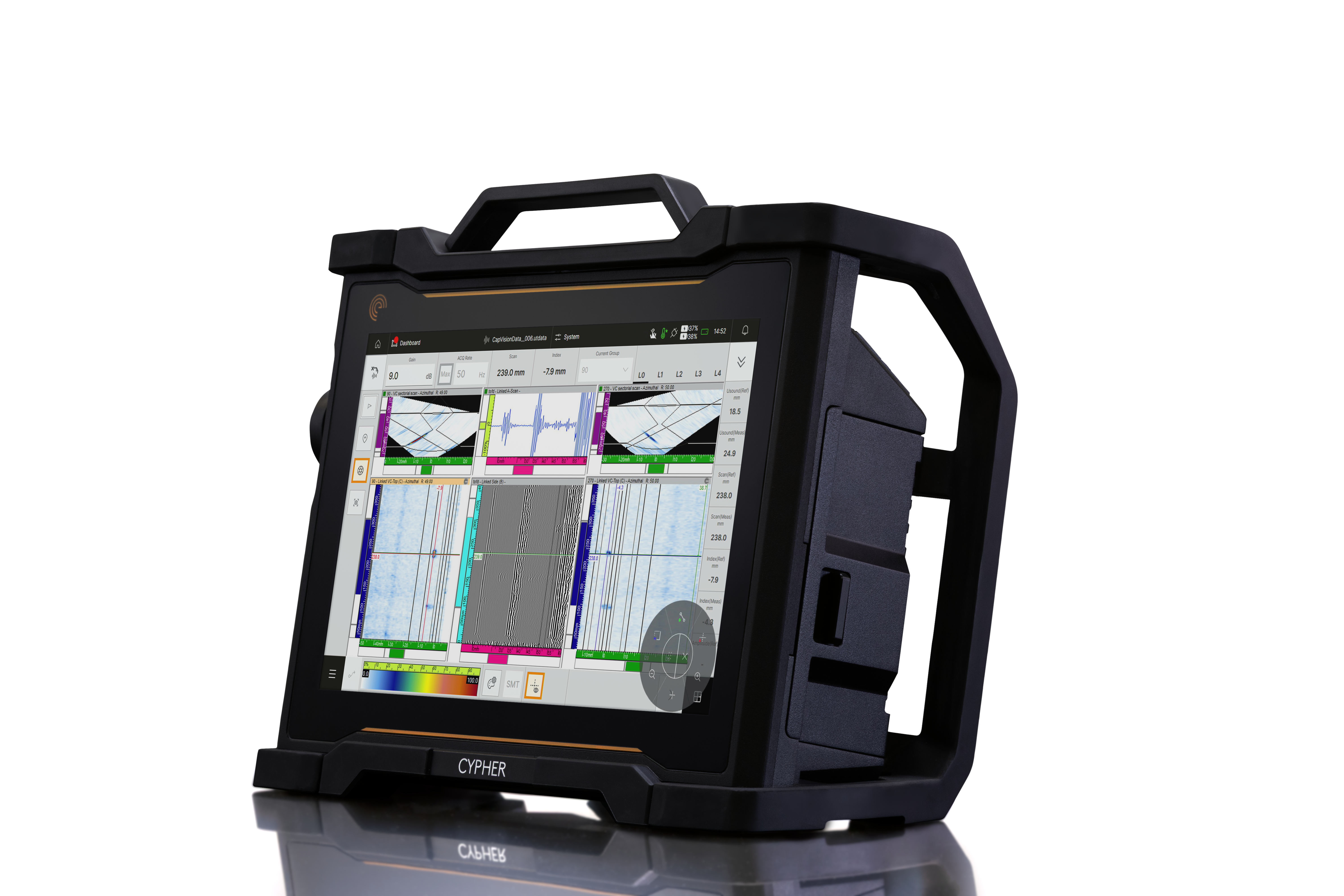
Benefits
- Improved probe design offers easier to interpret data and better discontinuity detection and sizing for more reliable inspection results.
The improved detection and sizing capability, including transverse and skewed reflectors, offer a scalable test solution that provides more reliable data through streamlined setup, acquisition, and data analysis which in turn equals less time spent with setup, calibrating equipment, and performing the friction stir weld inspection in newly manufactured aerospace assets. With the option to go from one probe and acquisition unit up to three of each, inspection times can be reduced by a factor of three. Depending on the exact nature of the inspection and the application, this aerospace inspection solution is easily modified to get the maximum performance when and where it is needed. Contact us to discover how to keep weld inspection program Beyond Current!


