Explore Eddyfi Technologies Product Lines
Guided Wave Testing: Now Finding a Needle in a Haystack
Ask an expertGuided wave testing, or GWT, uses low-frequency ultrasound operating between 20-150kHz compared to the MHz frequency range for conventional ultrasonics used for thickness checks. This allows the ultrasound to be broadcast away from the tool and axially along the pipe in GWT. When this broadcast ultrasound encounters a change in cross-section, the change in acoustic impedance of this region causes an echo of sound to return to the tool for detection. Using the welds on a pipe for calibration and comparing amplitudes of other signals to these welds, it is possible to indicate the severity of any corrosion detected. Moreover, using additional advanced methods such as C-scan imaging techniques and, in Eddyfi Technologies’ case, a unique secondary focusing method, it is possible to give angular positioning and circumferential extent.
Most experience and use of guided waves have been for Long-Range Ultrasonic Testing (LRUT). Lower frequencies (20-50kHz) are used for screening pipelines with ranges greater than tens of meters achieved. These methods and the procedures for this type of inspection are well established and implemented within industry with global standards published, including international standards such as ISO 18211. However, guided waves are for more than just LRUT, as demonstrated in this application for drill riser inspection.
The Challenge
Explore the applicability of a long-range ultrasonic testing solution for shorter ranges such as weld to weld or flange to flange inspection.
This application explores the use of guided waves for Medium-Range Ultrasonic Testing, or MRUT, where frequencies in excess of 100kHz are employed. At these frequencies, there is improved resolution due to the shorter pulse length of the ultrasound transmitted. An improved tool and signal to noise allows for improved sensitivity, detectability, and positioning of defects, making inspection over a defined shorter range possible, for example, weld to weld or flange to flange inspection where test lengths are up to 15 meters (50 feet) depending on conditions.
A client provided a calibration pipe used for the pretesting of NDT inspection equipment for drill riser testing. The pipe was 114-millimeter (4.5-inch) diameter schedule 80 wall thickness (8.56mm/0.337in). The length of the pipe was 1.83 meters (6 feet) and had eight 1.5-millimeter (1/16-inch) drilled holes at 45° different angular positions and 76-millimeter (3-inch) separation along the pipe. There was a thinned area of pipe where thickness had been reduced by a maximum 1.5 millimeters (1/16 inches) gradually over a 76-millimeter (3-inch) length. A schematic and photograph of the test pipe are shown in Figure 1.
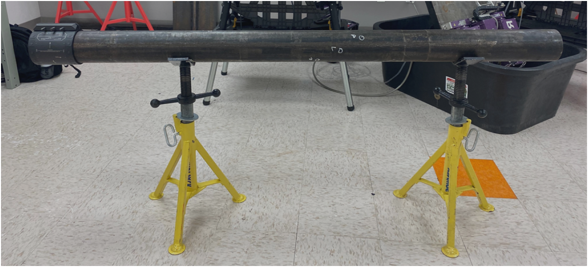
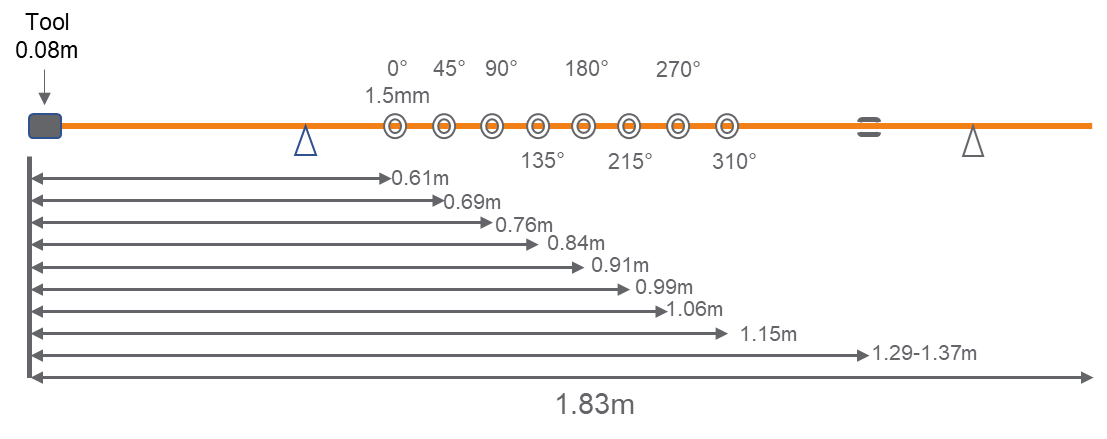
Figure 1: Diagram and schematic of the 114mm/4.5in test pipe
A close-up of the defects included in the pipe is given in Figure 2, showing the diameter of the holes and the thinned area.
Learn more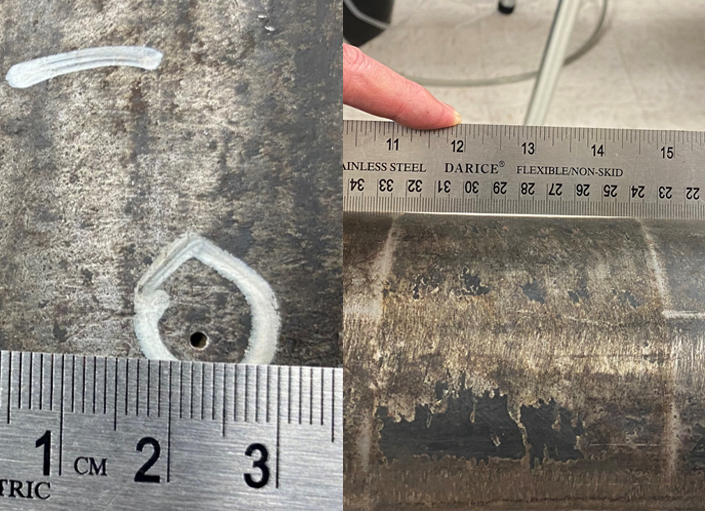
Figure 2: Close-up photographs of the drilled holes and the thinned areas requiring detection
The Solution
An improved tool and signal-to-noise enables improved sensitivity, detectability, and positioning of defects, making assessment over a shorter range possible.
The Sonyks™ guided wave system (Figure 3) is the first equipment on the market to use both piezoelectric and magnetostrictive transduction methods for generating guided waves. Both methods have pros and cons, with the piezoelectric transducers being most suitable and optimal for the LRUT type inspection and larger diameter pipes. In comparison, the magnetostrictive transducers are optimal for small diameter pipes and expand into high frequencies such as MRUT.
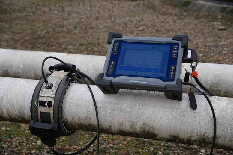
Figure 3: Sonyks instrument with the Piezo tool on site
The magnetostrictive collars are comprised of a magnetic strip and an Electro Magnetic Acoustic Transducer (EMAT) coil housed in a clamp. Torque is used to provide mechanical coupling when inducing the ultrasound into the pipe. There have been several limitations to using magnetostrictive guided waves in the past, particularly the need for bonding the foil to the pipe and the difficulty in extracting the flexural information from the collected data. These issues have been overcome with the Sonyks Magneto-tools resulting in a low-profile simple collar, as shown in Figure 4.
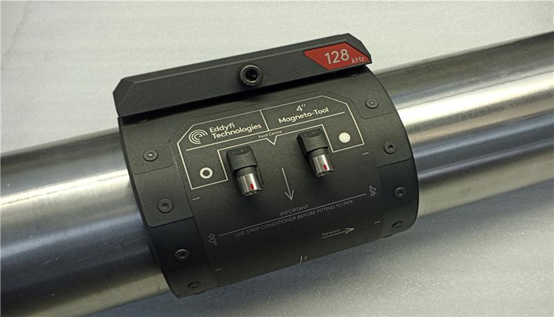
Figure 4: Sonyks Magneto-tool for 100mm/4in diameter pipe and 128kHz test frequency. The tool is lightweight, low profile and can be quickly installed.
The signal-to-noise ratio improvements at higher frequencies and its low profile make this tool ideal for inspection of small diameter pipes (40-200 millimeters/1.5-8 inches) with limited radial clearance.
The 128kHz, ASME 100-millimeter (4-inch) Magneto-tool with Sonyks software was employed for this inspection. Due to the short length of the sample, the tool was positioned at the very end of the pipe such that the pipe end would be in the dead zone of the data making interpretation easier. In the field, the pipe lengths would normally be longer. The tool would be situated at approximately one third along the length. It was possible to inspect forwards and backwards simultaneously.
Due to the new data collection methodology, a combination of Full Matrix Capture (FMC) and broadband chirp was utilized. Data was collected using the Sonyks instrument, and interpretation was carried out on the integrated screen using the Sonyks software. Once the data collection is completed, all the data ever needed has been captured—even the secondary focusing.
On interpretation, the signal-to-noise ratio on this sample was excellent, and it was possible to detect all the defects within the sample. The collection's pulse length was not quite short enough to resolve all eight defects individually. The C-scan image shows six colour spots corresponding to the location of the eight defects. However, it is evident that these six spots rotate around the pipe in precisely the same pattern and position of the defects in the pipe. It was also possible to detect the thinning of the pipe between 1.29 and 1.37 meters (5 and 5 feet 3 inches) from the datum of the pipe end. This area is a band in the C-scan that is fully circumferential around the circumference. The data displayed in the software is displayed in Figure 5.
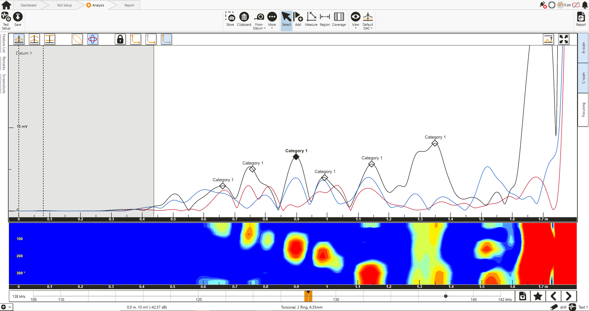
Figure 5: A-scan and colour map of the data showing the defects in the pipe. The coloured spots correspond with the defects. The rotation of these spots matches identically with the defects' rotation on the pipe.
Secondary focusing was used to see if further information and resolution of the defects could be discerned, and by altering the focal length and focal distance of the data, it was possible to view each defect in turn and map the rotation of all eight defects around the pipe from 0° to 315°. These focus plots are displayed in Figure 6.
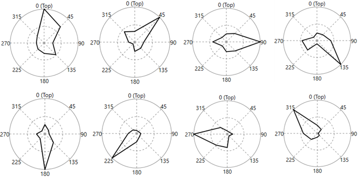
Figure 6: Focusing shows the defects' rotation with distance from 0° to 315°
In this example, the signal to noise of the tool was excellent, such that it was possible to find a 1.5-millimeter (1/16-inch) hole on a 114-millimeter (4.5-inch) diameter. This equates to 0.4% CSA.
The test shows that Sonyks with the high-frequency Magneto-tools has the potential to find very small (1.5mm or 1/16in) localized defects over a defined inspection range. From the results, it is anticipated for a clean pipe that this sensitivity could be applicable along a pipe length of up to 12 meters (36 feet) inspecting weld to weld, flange to flange, or socket to socket fittings the most appropriate application.
See pricingBenefits
- The principle and sensitivity are transferable to other pipe sizes and materials as a potential solution for consideration to other important inspection challenges within other industries.
Although this pipe was designed as a calibration test pipe for drill riser inspection, the principle and sensitivity are transferable to other pipe sizes and materials as a potential solution for consideration to other important inspection challenges within the energy, chemical, food, and even pharmaceutical industries.
For example, particularly interesting would be to inspect stainless steel pipe where corrosion from chloride attack or microbiological induced corrosion can lead to very localized corrosion. The MRUT methodology can detect this when inspecting the pipe section by section.
In addition, a targeted inspection of U-bolt clamps by MRUT is another highlighted area of interest by the industry. Small diameter pipe clamps are difficult to inspect. Using MRUT would negate the need to interfere by lifting or using radiography.
Finally, an inspection of air to soil interfaces where the first few inches of inspection are important for detecting corrosion is another example of utilizing the attributes of this technique.
Therefore, targeted inspection on any small diameter pipe 40 to 200 millimeters (1.5 to 8 inches) would be interesting for this technique.
For further discussion and information, please contact us.