Explore Eddyfi Technologies Product Lines
Improved Phased Array UT Inspection of TKY Joints
Ask an expertFillet welds, or T-joints, are widely used in different construction sectors, storage tanks, naval components, bridges, and more. A failure in a fillet weld may lead to heavy loss or wastage of materials contained by a tank, or it may have other major consequences to the fitness-for-purpose of assets. T-joints and similar weld geometries have always presented a challenge for ultrasonic testing, but there is now a way to validate that coverage is adequate and to reduce the adverse effects of this configuration.
The Challenge
The structural integrity of fillet welds is difficult to assess given their intricate nature. Determining the right scan plan to ensure the entire joint is inspected proves problematic.
Traditionally, ultrasonic testing (UT) of fillet welds has always been possible, but somewhat impractical to say the least. The reason is simple: the geometry of the joint makes it very complicated and can lead to questionable results. Depending on the throat thickness, significant volumetric defects and penetration can be assessed with UT, but reflections and achieving proper coverage remains problematic. As per the American Welding Institute (AWS), T-joints in which the angle between joined parts is greater than 100° or less than 80° shall be defined as “skewed T-joints”, and those can be even more challenging to inspect with UT. The complexity of the geometries makes it difficult to determine scan plans that ensure full coverage of the joint. Multiple echoes coming from various places of the joint also make analysis complicated and tedious. This leads to lower efficiency, and unfortunately, a lower Probability of Detection (PoD).
The Solution
A unique application embedded on portable phased array units allows inspectors to effectively and efficiently define T and Y joints.
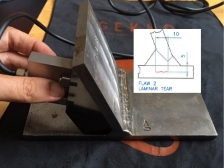
Typical T-Joint Sample
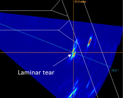
Counterintuitive Imaging
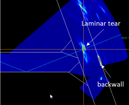
Auto-adjusted Imaging
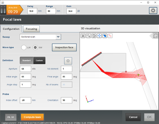
A complete software tool has been implemented in advanced portable phased array (PAUT) instruments in order to facilitate inspections of T-joints. It allows one to define T-joints (including skewed configurations), with various preparations and single or double bevels. It is now easy to calculate the optimum scan plan directly on the equipment to guarantee complete coverage of the welds. The probe can be positioned on any surface of the joints (web, tee, etc.) depending on the accessibility of the inspection. Cross-section overlays are calculated and superimposed with the ultrasonic data making it possible to precisely position and size indications. It is also possible to account for rebounds off the various surfaces of the joints.
The proposed solution includes the following items:
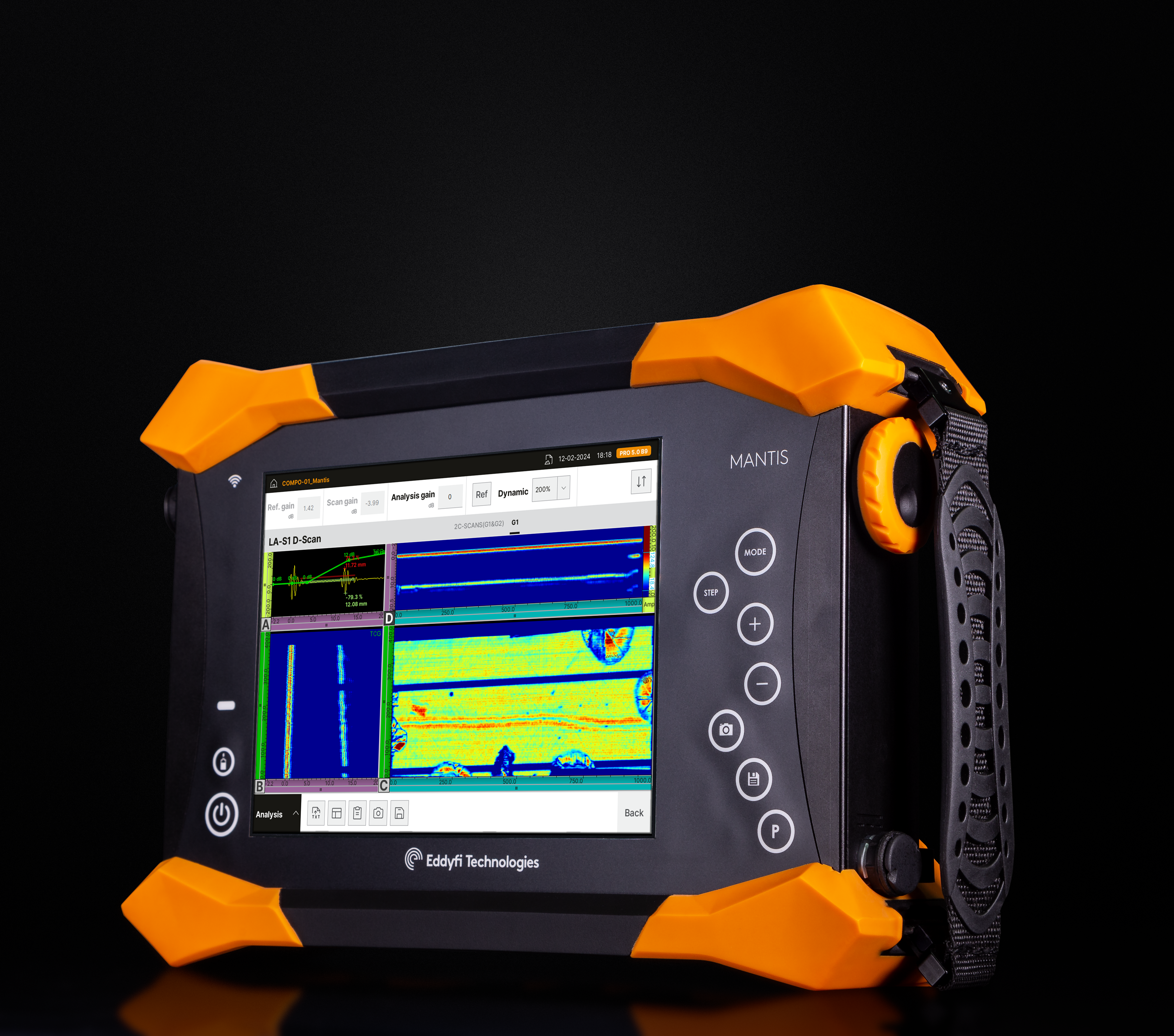
- Mantis Expert PAUT system to efficiently define TY joints, determine scan plans and reconstruct data in the geometry of the TY joints
- 1- or 2-axis scanner (automated or not) to move the probe along any of the TY joint surfaces
- Linear or matrix array or even DLA or DMA for stainless steel configurations.
Eddyfi Technologies proposes a unique solution for the ultrasonic inspection of TY joints commonly found in the oil and gas, metallurgy, and marine industries. Our solution helps operators simplify inspections and save time. Contact us to learn more about maximizing inspection efficiency today.
Contact usScan plans are easy to configure
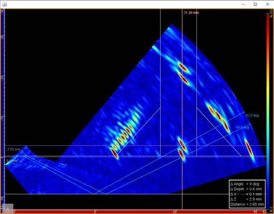
PAUT imaging with reflection for intuitive interpretation
Benefits
- Full volumetric inspection
- Improved Probability of Detection (PoD) and characterization accuracy
- Increased productivity
It is possible to define scan plans on the equipment accounting for the geometry and rebounds off the various surfaces of the joint. Visualisation of the acoustic path and location of the focus points allows for optimal positioning of the probe (offset, etc.) for ideal inspection procedures. Full coverage of the fillet welds is ensured with real-time sectorial or linear data superimposed on the overlay of the TY joints. Adapted scan plans particularly focused on the right location maximizes the sensitivity of detection of defects including smaller flaws. Proper reconstruction in the overlay of the TY joint enables perfect positioning and sizing of indications. An easy-to-use interface allows fast geometry and scanning setups. Optimal probe positioning and delay laws are quickly calculated on the equipment minimizing time for procedure development. Analysis time is also greatly reduced thanks to TY weld overlay and folding of the sectorial scans to consider rebounds.