Effective Thermal Fatigue Cracking in Pipeline Branch Connections
Ask an expertEnsuring the smooth operation of pipelines responsible for transporting contents throughout different areas of a process plant depends on regular assessment of the pipework including all branch connections. Because pipelines and other factory components are exposed to cyclic thermal stresses like those incurred from extreme temperatures or condensate and steam system contact, they are more susceptible to fatigue cracking. To maximize productivity in an economy that demands efficiency, Non-Intrusive Inspection (NII) is necessary to determine Fitness-For-Service (FFS) of these online assets.
The Challenge
Deliver better data results from examination of the typically difficult-to-access inside surface of branch connections.
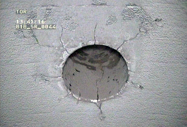
Thermal Fatigue Cracking
Thermal fatigue cracking, or TFAT, damage is a real threat to branch connections, and conventional A-scan ultrasonic techniques are the current NII method for detecting this defect. The traditional Non-Destructive Testing (NDT)approach uses a tangential ultrasonic technique with a conventional search unit to locate the bore of the main pipe, the crotch corner area of the bore, and the bore of the branch pipe. An operator uses an array of single angle probes to locate cracking emanating from the regions of interest. Although this technique has proven to be successful in detecting damage, the geometry of certain branch connections adds complexity to this inspection region and can restrict full coverage. Furthermore, accurate sizing of damage can be difficult.
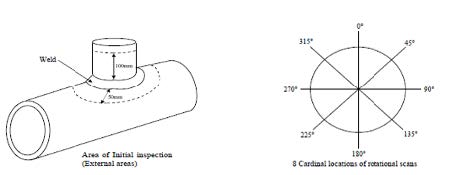
Overview of the typical inspection area
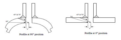
Inspection coverage of a typical branch connection
The Solution
Phased array ultrasonic testing technology improves upon current non-intrusive methods of inspection.
 Sectorial scan from 0/180 position with phased array response
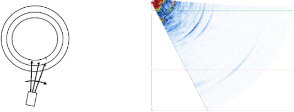 Tangential scanning showing phased array response with no reflectors present
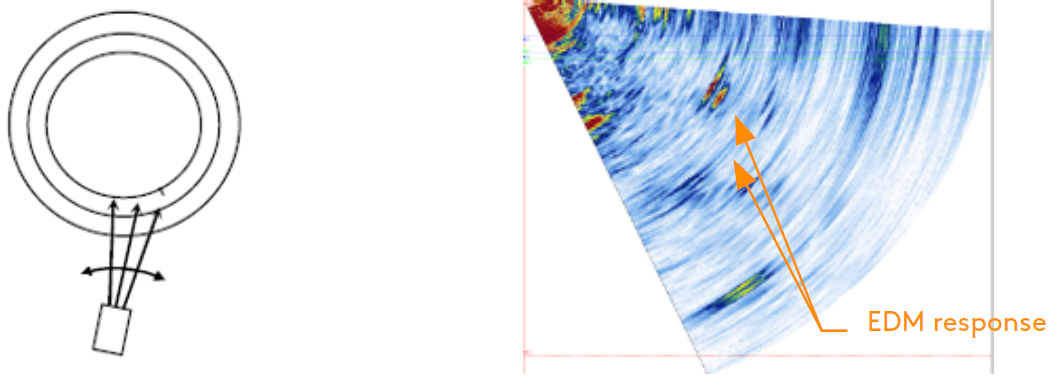 Optimized tangential scanning showing maximized phased array response from an EDM notch reflector
Phased Array Ultrasonic Testing (PAUT) technology uses a linear array of piezo elements individually mounted in one complete probe housing. Each element can be individually pulsed with an accurate timing sequence (focal law). The phasal interference of wave fronts from each adjacent element can be used to form a bulk wave that is steered or focused based on the time delays of the voltage pulses between each element. The use of multiplexing and PAUT probe technology allows for numerous inspection angles and focal laws to be collected simultaneously.
The resulting bulk wave can take two forms: sectorial or linear. In a linear scan, all focal laws employ a fixed angle beam, whereas sectorial scans use fixed apertures and steer through a sequence of angles.

Sectorial angular sweep (left), fixed angle linear scan set to zero degrees (right)
The PAUT technique used a swept angle sectorial scan for a lab trial with EDM notches. The operator placed the flat-shoed 1D linear phased array probe in the same positions used in the conventional inspection for comparison. The Cypher® 64:128 instrument, 16 element 4Mhz small footprint probe, and incorporated wedge with a 42-degree incident angle were used for this application.
First, the crotch corner from each cardinal position was individually located, the greatest response being from the 90 and 270 position. The focal laws selected were governed by the part geometry to ensure the entire pipe bore was evaluated. Next the probe was rotated to the branch tangent. If no reflector was present (EDM notch), there was no response within the Sectorial Scan, or S-scan. Manipulating the probe maximized the phased array response when a recordable response was detected.
The operator then sized detections with recognized signals caused from the top and bottom of the defect. The damage typically breaks the pipe inner diameter (ID) surface and therefore creates a corner type response which can be easily recognized. The operator interpreted diffraction signals generated from the tip of the flaw which allowed measurements between the two signals. Length sizing requires operators to keep the probe perpendicular to the defect/reflector and assess the length by using dB drop method; it should be noted that due to the complexity of the joint construction, the radial extent is given with +/- 5 millimeter (0.2 inch) margin of error.

EDM slots in ID bore (left), phased array response showing corner response and tip diffraction from EDM slot (right)
Ask an ExpertAll EDM notches on the main pipe bore and branch bore were successfully identified with inspection coverage improved for all parts; 100 percent coverage of the main pipe bore, crotch corner, and branch connection bore are shown for all thicknesses. Although detection capability using a multi-angle beam increased, it is important to note that defects must be favorably orientated for detection.
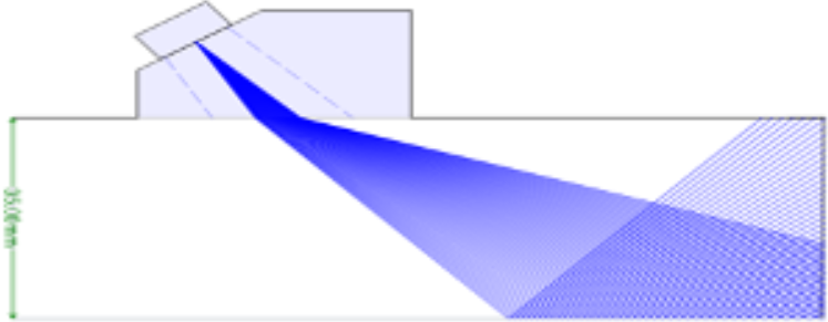
Sectorial scan at 90/270 position on 35mm sample - angles from 40° to 70° showing full coverage of pipe bore, crotch corner and branch bore
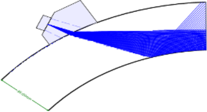
Sectorial scan at 0/180 position on 35mm sample - angles from 40° to 65° showing full coverage of pipe bore, crotch corner and branch bore
The PAUT technique described was implemented on a known damaged plant item and validated all indications recorded during a conventional UT inspection.
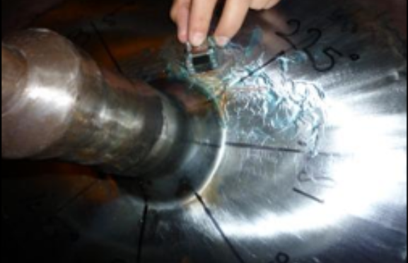
Probe orientation for defect located in position 225°
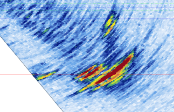
PAUT S-scan response from crack indication at location 225° (indication measures at 17mm through wall)
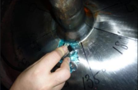
Probe orientation for defect located in position 135°
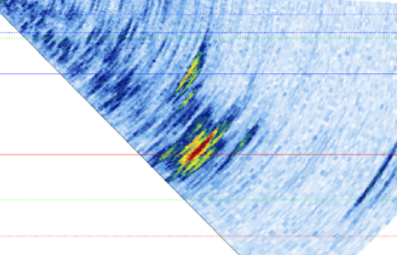
PAUT S-scan response from crack indication at location 135° (indication measures at 14mm through wall)
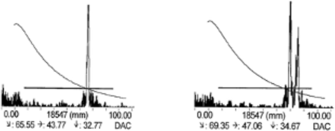
A-scan response from crotch corner (left), response from defect found at branch tangent (right)
See pricing
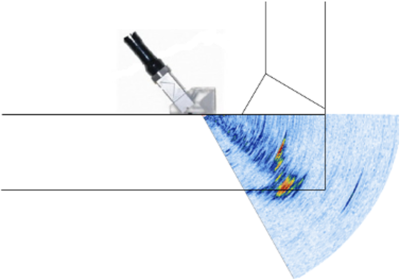
Phased array crack response from tangential scanning
Benefits
- Advanced ultrasonic instruments offer better coverage and defect characterization for more informed decision making.
Phased array ultrasonic testing has proven itself as a very powerful tool for detecting, sizing, and displaying the thermal fatigue cracking found within main pipe bores of branch connections tested. The high angular resolution combined with the high frequency probe provides a unique image of crack morphology not available with manual ultrasonic testing.
Interested in how our comprehensive advanced inspection portfolio solves broader non-destructive challenges across the pipeline sector? Download our editorial to stay Beyond Current!


