
Most applications involving the Total Focusing Method (TFM) technique have been applied to defects located in the volume or along the backwall of test components. These defects include High Temperature Hydrogen Attack (HTHA) and Hydrogen Induced Cracking (HIC) found during weld inspection.
We know that it is also possible to use TFM to detect and size indications along a scanning surface using a rebound off the backwall with an indirect mode such as TT-TT. Sometimes the component is too thick or the backwall too uniform to use a reflection, so it may be in the best interest to use a direct path.
After being introduced into Codes and Standards, TFM has slowly started to become a recognized ultrasonic technique that brings advantages over conventional UT and phased array technology. Its aptitude to focus energy everywhere in a Region Of Interest (ROI) improves the sensitivity of detection of small defects and tip diffractions from crack extremities.
Until now, most applications have used bulk waves to inspect the volume and surface opposite to the scanning surface. It is also possible to detect and characterize defects along scanning surfaces using an indirect mode, such as the TT-TT, using a reflection off the backwall surface. This mode requires a flat backwall (for systems that cannot take irregular surfaces into account) and can imply a long distance of propagation for thick components.
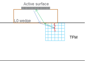
We present another way of using TFM to detect and size indications along the scanning surface using a direct mode. To demonstrate, we use a L0 wedge and longitudinal waves which tend to be more sensitive to tip diffractions. The ROI is not positioned directly underneath the active surface but is positioned slightly before to avoid having the defect mixed with the front surface echo. We calculate a TFM using the direct mode L-L with a grid size that respects the Amplitude Fidelity.
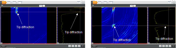
This technique was first used with calibrated notches to evaluate sizing capabilities. The following images show the TFM image obtained for a 2.5- and 8-millimeter (mm) notch in a stainless steel sample. The probe used is a 7.5 MHz PAUT probe with a 20-mm L0 wedge. The tip diffraction echoes are clearly visible in both cases, their Signal-to-Noise Ratios (SNR) are measured at 17 and 11 dB, respectively. Sizing can be done easily using the echodynamic along Z that projects the maxima along the depth axis. Defects were sized at 2.51 and 8.13 millimeters, respectively.
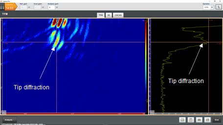
The technique was then applied to size a 1-mm notch. We used a 10 MHz probe. Using the echodynamic along Z, we size the defect at 1.1 millimeters. The TFM technique is capable of sizing small defects with the combination of an appropriate probe, wedge height, and aperture.
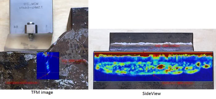
Finally, we looked at a real fatigue crack that occurred along a filet weld. We used 7.5 MHz with a L0 wedge again. We performed a mechanical scan along the defect to see its evolution and the capability of the technique. The following image shows the position of the TFM image with respect to the fillet weld. The front of the wedge was slightly machined to bring it as close as possible to the weld. We can see the top diffraction echo, meaning that the defect breaks the surface, and several diffraction echoes from the facets of the defect.
We superimposed the Sideview on a photo of the test piece. The Sideview is a concatenation of the TFM image along the displacement which allows us to follow the various diffraction echoes, including the deepest one, and thus characterize the fatigue crack; the height of the defect varies between 6 and 9 mm.
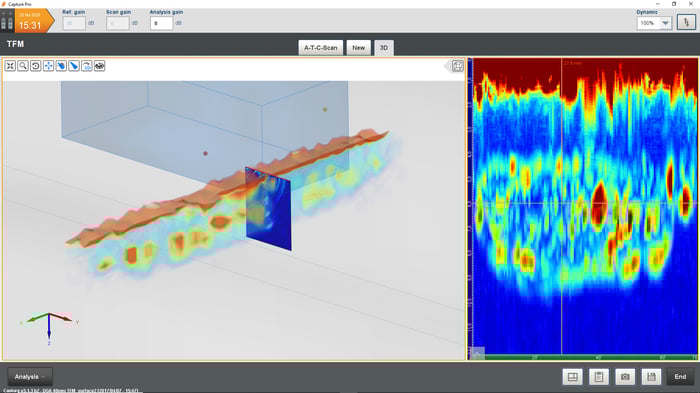
The 3.1 version of Capture™ software allows exporting data in 3D. The following image shows the previous data exported in 3D superimposed with a TFM cross-section for the position where the defect is the deepest. The 3D view shows the morphology of the defect.
When it comes to surface crack detection and characterization, trust the M2M Gekko®, Mantis™ and Panther™ powerful TFM instruments to leave no flaw left undiscovered. This is just one example of how diverse the Total Focusing Method technique is for the effective inspection of different defects. Contact us to discuss how our advanced solutions can help optimize your inspections and subscribe to our blog to see how we continue to exploit TFM for more and more applications.