
Longitudinal welded pipes are used in various industries. Like other welds, they need to be inspected for defects both at manufacturing and for maintenance purposes. Circumferential and plate weld inspections are based on tools that use flat surface models. These tools include wedge delay calibration, delay law calculation, and corrected scan representations (E-scan, S-scan, and Compound scans) with weld overlay. These tools cannot be used directly with longitudinal welds. We present the Beyond Current solution.
Wedge Delay Calibration
Challenge
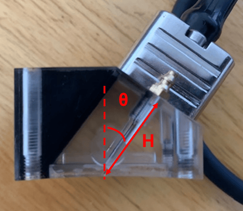
PAUT and TFM inspection of longitudinal welds use special wedges called Circumferential Outside Diameter or COD for which the curvature of the wedge is machined to match the OD curvature of the pipe.
To calculate delay laws properly, the angle and height of the wedge need to be calibrated carefully. Improper curvature measurements of the angle and height lead to wrong delay laws resulting in wrong angles and poor focusing.
Check out the Eddyfi eStore for instant pricing for all our ultrasonic probes.
Delay Law Calculation
Challenge
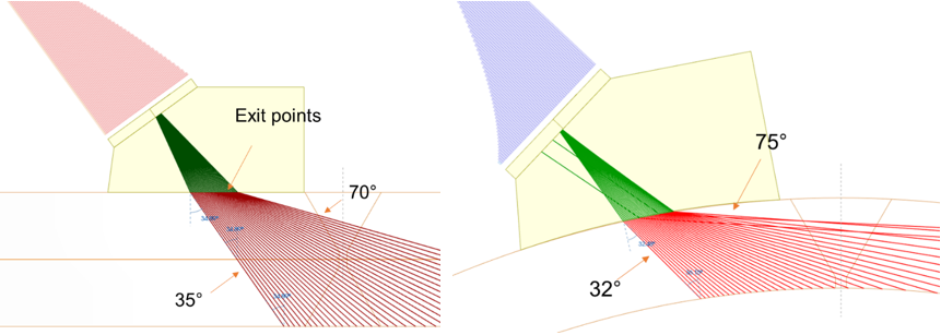
Delay laws allow the generation of ultrasonic waves at desired angles with or without focusing. When dealing with flat and circumferential welds, a scan plan is determined to obtain optimum detection of indications inside the weld (learn how to set the perfect scan plan for weld inspecting using TOFD, PAUT, and TFM here). Typically, a 35° to 70° sectorial scan is very common to obtain beams normal to the bevel on the second leg and high angles inspecting the root of the weld. Delay laws consider the exit points along the top surface for each angle. If we import these delay laws for a curved component, for example a 500-millimeter (20-inch) pipe, not considering the curvature leads to angles different than the original 35° to 70° ones, 32° and 75° in this example. This means that indications could be mispositioned.
Solution
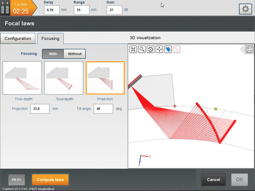
Capture software’s delay law calculator considers the curvature of the component. It is functional for all probes: linear, matrix, dual linear array (DLA) and dual matrix array (DMA). It is possible to visualize focusing points after skipping off the backwall in order to position them perfectly. This allows defining the scan plan and ensuring full coverage of the weld. Several focal modes are available to focus the energy wherever the operator wants.
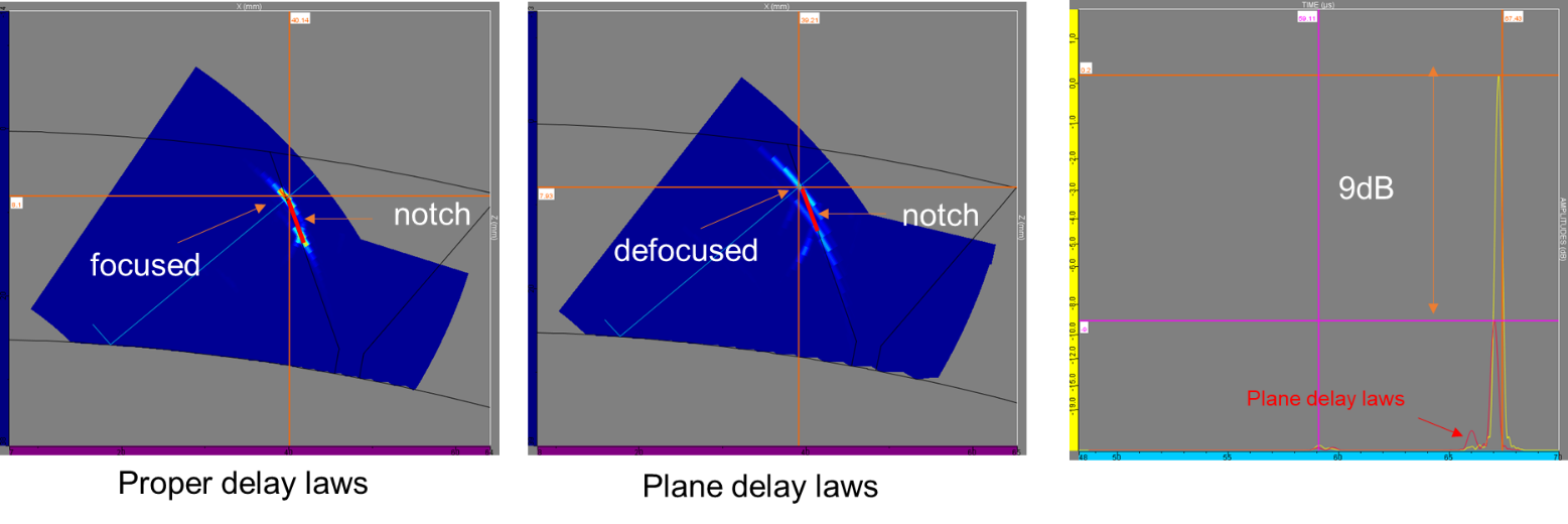
Considering the curvature allows the generation of proper angles but also focusing on the right location. The following images show the beam calculated for the 42° angle. When we consider the curvature, the beam focuses along the bevel after a rebound off the curved backwall. On the contrary, using plane delay laws leads to an unfocused effect on top of the wrong angle (44°).
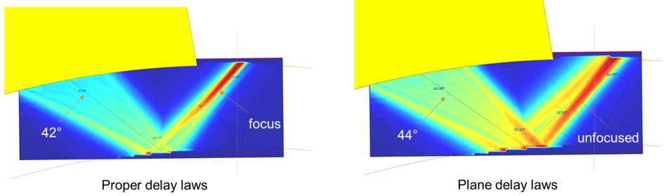
Looking at the results for a notch along the bevel, we can see that using plane delay laws leads to a drop of about 9 dB in terms of sensitivity due to the unfocused effect.
Learn more about optimizing signal response through focusing in this blog.
Image Representation
Challenge
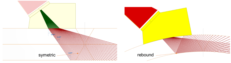
For plate and circumferential welds, PAUT data is usually represented with an overlay of the weld. The second leg is typically represented with a symmetric image of the weld as reflections off the backwall are coming from a flat surface. For longitudinal welds, it is not possible to use the same symmetric image as ultrasounds reflect off a convex surface.
Solution
Capture software allows the representation of linear, sectorial, and compound scans considering the rebound off the backwall and top surface. Ray tracing is done using the exit points calculated by the delay law calculator and the specific reflection angle of each beam. The following image shows the ray tracing of a 35° to 75° sectorial scan for a 500-millimeter (20-inch) pipe. The angular resolution in the second leg is unevenly distributed increasing for larger angles. This potentially lowers the spatial coverage which may result in poor probability of detection. This effect is amplified for small diameter pipes. The ray tracing is thus very important for operators to define their scan plan properly.
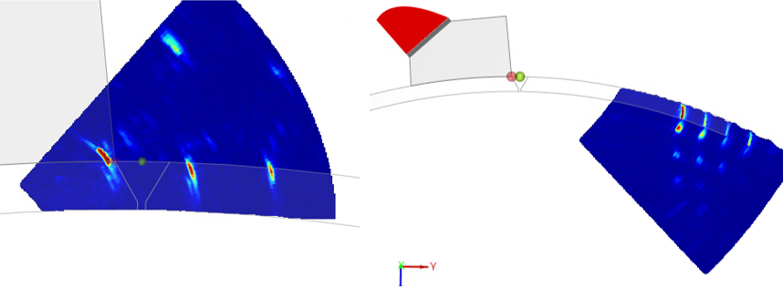
Using the ray tracing, it is possible to represent E-scan, S-scan, and Compound scans as folded images. The following image on the left shows OD cracks positioned correctly on the OD surface of a 17.7-inch (450-millimeter) pipe. Capture also considers multiple skips folding the image many times. The image on the right represents the same defects seen after four skips between the backwall and OD surface. This can be useful when an obstacle prevents positioning close to the weld.
 Another example of ray tracing can be seen in this application note on how to better assess TY fillet welds with actionable insights.
3D Export
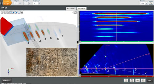
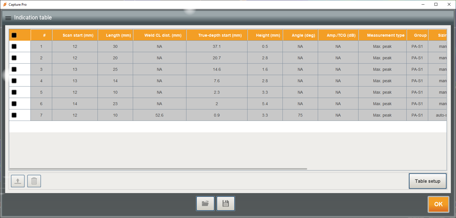
Since Capture version 3.1, it is possible to export data in 3D view taking into account the rebounds off the various surface; this is also valid for curved surfaces. The following image shows the data export of seven OD defects detected, the Topview, and the S-scan.
Auto-sizing
The auto-sizing tool is also fully compatible with longitudinal welds.
For longitudinal weld inspection, Capture data acquisition and analysis software offers all the tools necessary to perform complete non-destructive testing inspections. From wedge delay calibration to delay law calculation and visual representation, operators have all the means to optimize their scan plans. All these tools are available on both the Gekko® and Mantis™ portable flaw detectors—even on the entry level unit. Moreover, Capture software extends to Panther™ for unparalleled performance. Combining the hybrid LYNCS™ scanner with our PAUT probes and advanced analysis tools truly offers operators the full package for longitudinal weld inspections.
We invite you to check out the available resources by the Eddyfi Academy and contact us to learn how best to integrate our advanced inspection solutions into your next job.