
Cracking or corrosion doesn’t necessarily mean that a component must be repaired or taken out of service. Fitness-for-Service (FFS) is a standard used in the oil & gas industry for in-service equipment to determine its capability for continued use. FFS helps engineers decide if a flaw is acceptable or unacceptable and whether assets can be operated safely until the next planned outage. One of the most important inputs are the dimensions of the defects found in a structure.
When using ultrasonic testing (UT) techniques, being conventional, Time-of-Flight Diffraction (TOFD), Phased Array UT (PAUT) or Total Focusing Method (TFM), sizing can be done using various methods. International Standards such as ASME V or ISO explain the various ways to do it. Essentially, if tip diffraction echoes are observed, they should be used to determine the height of an indication. If there is no tip diffraction, then other methods such as amplitude drop, comparison to a reference, Time Corrected Gain (TCG) or Distance Gain Size (DGS) should be used.
With its new release, Capture 3.1 offers a tool that allows automatic sizing of defects based on a decibel drop method. The operator just circles the indication and the software automatically measures the length and height of the indication. Capture offers two ways to measure the amplitude drop.
The first is based on the maximum amplitude of the indication. Capture finds the maximum amplitude within the area of search and uses the height and length criteria entered by the operator to size the defect along both directions. In the following example, we use this method to size a lack of side wall fusion found during a TFM inspection. We use the typical -6 dB amplitude drop for both the length and height. Capture automatically adds it to the table of indications with all information (length, height, scan and index positions, etc.) necessary for assessment.
The second option is measuring the dimensions of an indication for which the amplitude is above an evaluation level set by the operator. This is essentially the technique 1 described in ISO 19285 (for PAUT) and ISO 11666 (for conventional UT), which is based on 3mm diameter side-drilled holes.
We illustrate with a PAUT inspection of a 0.5” V-weld. We used a 64L10-G2 probe with an SW55 wedge. We performed all the necessary calibration steps including obviously the TCG. According to ISO 19285, the evaluation level is -14dB below the reference level when using technique 1 (side-drilled hole) for evaluating the length of the flaw.
The auto-sizing feature exports customizable information in the table of indications including flaw length, height, position, maximum amplitude, etc.
We can use the acceptance criteria described in Annex A of ISO 19285 as an example to accept or reject the defect. Figure A.1 of this Annex shows the amplitude acceptance for 8-15mm thick test piece. The horizontal axis is the ratio between the length of the defect and the thickness of the test piece, and the vertical axis is the acceptance level (in dB with respect to the reference amplitude).
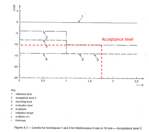
In our example, the ratio flaw length/thickness of the slag is 1.76; we see in the previous figure that the amplitude of the acceptance level needs to be -10dB or less than the reference value to be accepted. In our case, the maximum echo was measured at 4.2 dB above the reference value leading to a rejection of the flaw.
Rather than manually size indication using cursors, the auto-sizing feature allows quick sizing of indications detected during an inspection. The operator can customize the information exported in the table of indications and use it to quickly accept or reject defects based on Standards.
We’re dedicated to providing relevant content available when you need it and invite you to check out our Eddyfi on Demand platform filled with how-to videos, webinars, technical papers, and even some free training courses offered through the Eddyfi Academy. And as always, our experts are on standby to answer any of your inspection questions. Get in touch today!