
In this second installment on inspection speed optimization, I’m going to attempt to shed some light on the touchy issue of IRIS inspection speeds.
Find out how ECA probe speeds are superior to RPC probes’. You can also read about how to maximize RFT inspection speeds here.
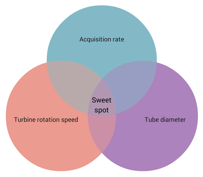
Striking a Balance
IRIS is a well known and well established technique for tube inspections. This is because, among other things, it can be used on ferromagnetic and non-ferromagnetic materials with no effect on performance, as the technique uses ultrasounds.
But, just as with other tubing inspection techniques, the IRIS inspection result reliability depends a great deal on the inspection speed at which the operator pulls the probe. The optimal IRIS inspection speed — the speed offering a 100% coverage of the interior of tubes — depends on a careful relation between the tube diameter, the IRIS probe rotation speed, and the test instrument’s acquisition rate.
The challenge is to strike a balance between the three to get reliable results.
That’s the sweet spot you’re aiming for.
The first parameter to consider in trying to hit inspection speed balance is the diameter of the tubes under test. When you inspect larger tubes, ultrasounds take more time to travel between the tube wall and the probe than in smaller tubes. This impacts the acquisition rate because ultrasonic waves must have enough time to travel between the transducer and the tube and back before emitting a new pulse.
The IRIS probe turbine’s rotation speed is directly related to the inspection hardware and the water pressure inside the tube. The maximum rotation speed depends on the number of data points the system acquires at every rotation. As a rule, the faster the turbine rotation, the faster you can pull your probe.
As mentioned above, the pulse repetition frequency (equal to the acquisition rate) must be lower in larger tubes to give ultrasonic waves time to make it back to the transducer before emitting a new ultrasonic pulse. The acquisition rate also depends on the type of hardware you are using. The acquisition rate is commensurate with the following relation:
(Ultrasonic velocity in water / (Tube ID + (Transducer-to-mirror distance) × 2)) × 0.8
0.8 is the safety factor accounting for some off-centering.
To reach the best balance between inspection speed and reliable results, consider that the ultrasonic beam’s diameter on the tube’s inner diameter (ID) is typically 1–1.5 mm (0.039–0.059 in) at the focal point. This means you should only pull the probe 1–1.5 mm (0.039–0.059 in) between rotations to obtain maximum coverage. This is the axial increment. Typically, inspection systems use a fixed number of acquisitions per rotation. In our case, 180 acquisitions/rotation.
So, using the following relation, you can determine the optimal pull speed for your hardware and tubes:
(Acquisition rate × Axial increment) / Acquisitions per rotation
So, for a typical 25.4 mm (1 in) tube, you can reach an acquisition rate of 18000 Hz. Using an axial increment of 1 mm/rotation and 180 acquisitions per rotation, we get:
(18000 acquisitions/s × 1 mm/rotation) / 180 acquisitions/rotation) = 100 mm/s [4 in/s]
That’s the sweet spot.
Take a look at our complete IRIS kits to see for yourself how they measure up or use our Tubing Probe Creator to find out just what probes are suited to your specific application.